Changing image tiles on menu in NAV Anywhere

Summary

Menu tiles represent a mobile process. Since version 4 of NAV Anywhere menu tiles are supported, and images can be displayed.

image_any_menu

Style sheets (CSS) are used to render web pages based on pre-installed CSS definitions. Menu tiles are displayed making use of this definition and the media library folder to display a picture.

Processes that are visible from the menu can be equipped with an image (not required) to provide an easy recognition of its functionality.

Example

An example will reveal how to include a picture on the tile. For two styles we have included media images that are or can be used.
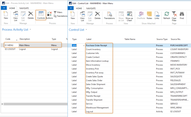
Menu Process in NAV

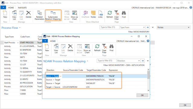
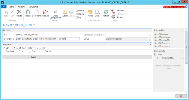
To display a picture, the Portal uses a CSS file to determine which picture to show. In the Process “Main Menu”, each Control has a specific label text which has to correspond with the MenuButton in the CSS file.
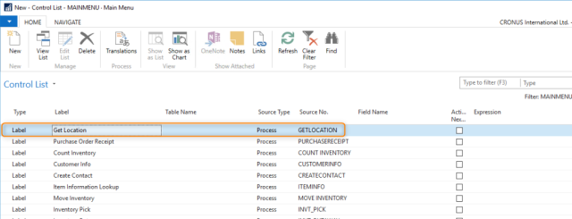
image_any_menucontrols

Add Process to Menu

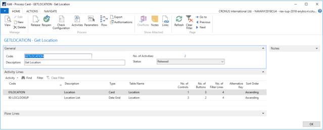
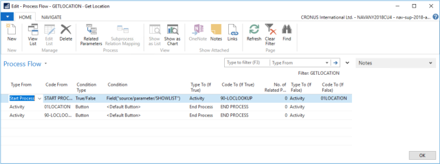
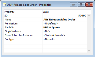
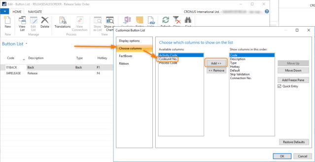
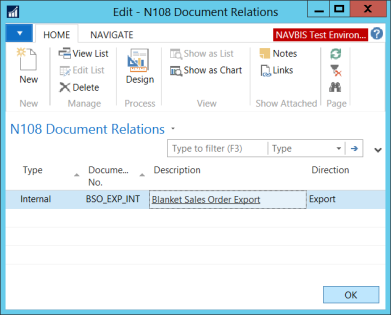
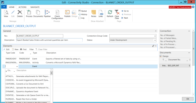
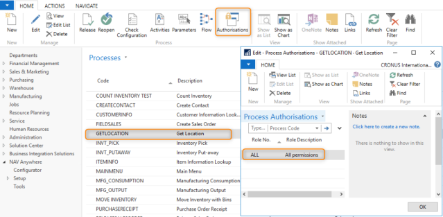
For this example, we add a new Process “Get Location” to the Main Menu Process:

image_any_addcontrol

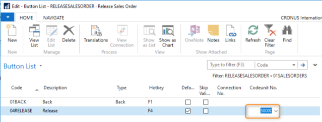
Release the Main Menu process.

Setup Role Authorization for Process

Make sure the process is authorized to ensure the process is visible in the menu:

image_any_authprocess

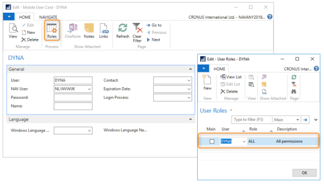
Check User for Role permission

Make sure the user has the corresponding Role, which includes the new process.

image_any_authuser

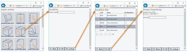
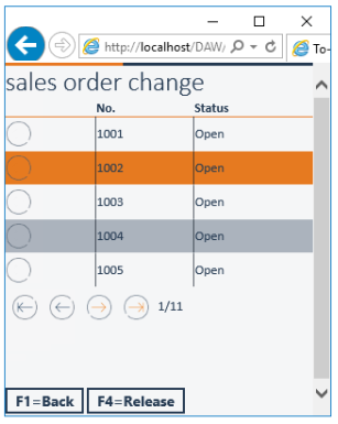
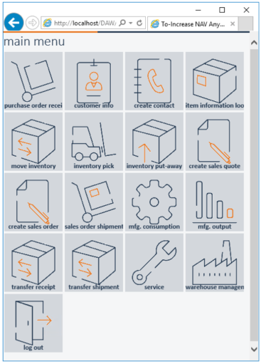
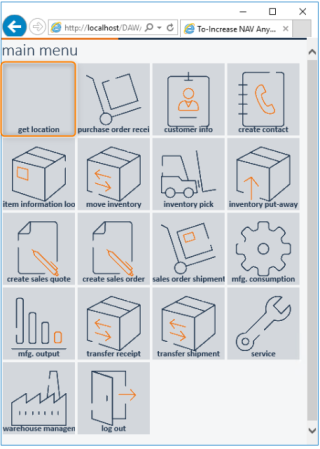
Result of adding process to Menu in browser

The actions above result in having an additional process available “Get Location”. No image is showing as we have not applied the required steps for this.

image_any_menublanktile

Locate Image

Displaying an image on the menu requires the use of the Media folder. In this example we will use an existing image, but new images can be added to fit the purpose of the process.

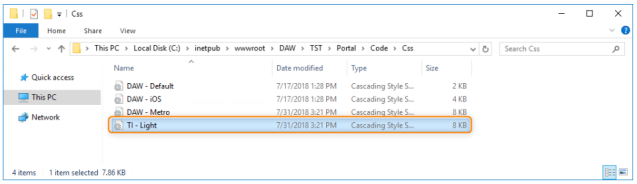
Located in the folder “TI – Light” you will find a library of tiles to choose from. (Default folder location: C:\inetpub\wwwroot\DAW\TST\Portal\Files\Media\TI – Light)

image_any_mediafolder

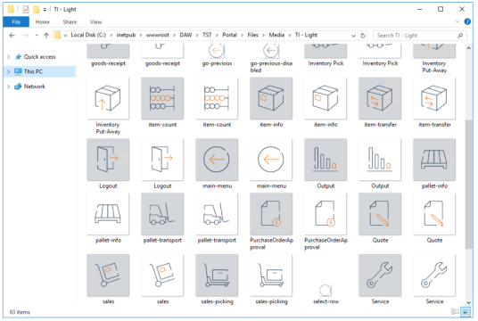
The Media folder contains a folder for each Style; in this example we use the “TI – Light” style to explain the behavior. The other style that supports images is “DAW – Metro”.

Add reference to menu tile and image

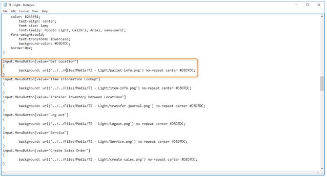
Open the CSS file and scroll to the input.Menubutton lines (Default folder location: C:\inetpub\wwwroot\DAW\TST\Portal\Code\Css\).

image_any_cssfolder

Add this code below the existing list of MenuButton definitions and change the values in orange:

input.MenuButton[value=”Get Location“]
{
background: url(‘../../Files/Media/TI – Light/pallet-info.png‘) no-repeat center #D3D7DC;
}

Note! Make sure the value is the same as the label on the control in the Menu (case sensitive).

image_any_cssmodification

Now save the file. If you have no permission to store the file, save the file in your Documents folder and copy the file to overwrite it in the destination folder (Default folder location: C:\inetpub\wwwroot\DAW\TST\Portal\Code\Css\).

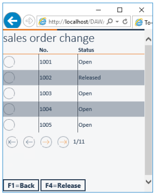
Result in the browser

The image should be visible when the menu is revisited.

image_any_menuimagetile

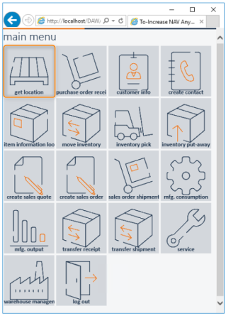
If the image is not showing immediately, please press Ctrl+F5 for a browser cache clearance.

Posted in Enterprise Mobility, NAV Anywhere | Leave a comment

Archiving in Connectivity Studio

Summary

It is now possible to archive the file after processing. This can be done with different settings. One of the new features is that the original file can be used to archive the file.

Archiving_Filewriter1

The following options for the “File Name” field are now available to provide flexibility in archiving the imported files:

Archiving_FileName

The archiving of an incoming file should be considered with checking the new “Use Original Message” field to ensure the content of the file remains exact after processing through the Pipeline.

Example

For applying the archiving feature, we use the TI_CS_ITEM.IN as the Connection and extend the Pipeline with an additional element, the FILEWRITER:

Archiving_ConnectionAdd

Add the Element

After the element “FILEWRITER” has been added, it needs to be configured. By selecting the element and clicking the “Edit” button.

The following actions are required:

  • Create an accessible archive folder to be able to write files to
  • add this folder to the “Folder Name” field
  • Check the “Use Original Message”

Archiving_Filewriter2

Next action is to compose the File Name. Click on the assist-edit in the field and a new page pops up:

Archiving_FileNameBlank

Clicking on the assist-edit on this page, the available expression options, it is possible to create a suitable File Name; to keep the original file Name there are three new expression options made available:

Archiving_FileName

We select the {FullOriginalFilename}. It is possible to add more expressions to compose a filename that will always be unique. We add the “.archive” as a plain text and finalize with the {MessageNumber} to make it unique.

Archiving_FilewriterFull

Close the element page.

Change the Pipeline

To include the archiving into the integration, the FILEWRITER element needs to be included into the Pipeline.

Archiving_ConnectionPipeLine

Open the Pipeline by clicking on the action on the Ribbon of the Connection.

Change the first Line:

Type To:             Endpoint
Code To:             FILEWRITER

Add a new line that contains the following:

Type From:         Endpoint
Code From:        FILEWRITER
Type To:             Activity
Code To:             MAPPER

Archiving_Pipeline

Run the action “Check Configuration” to ensure no issues with the configuration will occur. If entries show up after the check, please resolve. If you’ve taken the template “TI_CS_ITEM.IN” no issues should show up.

Process the Connection

Copy the sample file from the Installation package (Software\NAVBIS\Configuration Packages\Sample Files) “ItemDemo.xml”.

Archiving_SourceFolder

Run the Process action from the Ribbon:

Archiving_ConnectionProcess

The result is that the file is dropped to the Archive folder and has an additional archive extension.

Archiving_ArchiveFolder


Posted in BIS Concept, BIS General, Connectivity Studio, EDI Studio, Label Printing, Notification Management, Replication Management, Solution Center | Leave a comment

Sub Process Functionality in NAV Anywhere

Summary

It is now possible to switch to a different Process during the transaction of a Main Process. It behaves according to the diagram below:

SubProcess_Overview

After Activity 3 the Flow will direct the Main Process to start the Sub Process. After the Sub Process has been completed, the Main Process is able to continue with the defined Activity after the Sub Process in the flow.

Functionality

Sub Process Functionality supports calling other (sub) processes during the execution of the running (main) process. The Sub Process is nested into the Flow and will be seamlessly integrated into the main process, as it would be just another screen(s).

Sub Processes can be used for various purposes, but in essence it is designed to avoid redundancy in processes.

Brick Style

Several sub processes can be linked together by one “master” process, that links the “bricks” together.

Example – Location

The Pre-configured process MOVEINVENTORY and Sub Process GETLOCATION are used to show the purpose for using Sub Process Functionality. A good example is scanning/selecting the location. A number of To-Increase’s Pre-configured Processes are equipped with this functionality.

We have defined two screens; one card and one data grid screen. These are copies of the process from the Move Inventory Process, but now available in a separate process:

SubProcess_Process

The Flow will link the individual screens. Since the Main process triggers this Sub Process, we can decide if the sub process should start with a card screen or directly show the list of locations. Using the “Start Process” type, we can determine which screen to show:

SubProcess_Flow

Make sure a flow is configured to mark the end of a sub process, to return to the main process and that is by defining a flow line with an “End Process” type/Code.

The Sub Process will list a number of Parameters. These parameters are used to store values, but also to exchange information with the Main Process.

SubProcess_Parameters

It can be decided that a Sub Process only displays info, but it can also request info from the user and to be shared with the Main Process. The setup of exchanging the Parameters is done in the Main Process.

The Flow of the Main Process contains the flow line(s) that interact with the Sub Process.

MainProcess_Flow

Selection 1) shows that The at the “start process” of MOVE INVENTORY the flow directly shows the user the Sub Process “GETLOCATION”. Make sure that a flow line has been configured, Selection 2), that starts again from the Sub Process, to continue the Flow after the Sub Process is completed.

Because the MOVEINVENTORY process must scan the Location twice (one from and on to), the Sub Process is called twice with Selection 3) to start the Sub Process and Selection 4) when it returns to the Main process.

When selecting a Flow Line that will start a Sub Process on “True”, it is possible to link the necessary Parameters from the Main Process to the Sub Process.

SubProcess_RelationMapping

By selecting the appropriate Flow Line, the button “Subprocess Relation Mapping” will become enabled and by clicking on it, a new page will appear. All known Parameters from the Sub Process can now be linked to Parameters from the Main Process.

Three choices can be made regarding the Direction:

  1. If you only need to push the Parameter value into the Sub Process, but no need for a return value, the “Source->Target” can be used.
  2. If there is a need to receive the Parameter value from the Sub Process, the “Target->Source” is applied.
  3. If the Sub Process needs input from a specific Parameter, but also need to send an update for this Parameter, “Both” will be used.

If the Main Process doesn’t have a value, but an initial value is expected, the “Expression” field can be used for a value.

Result

The result is a Mobile process (MOVEINVENTORY) that is working seamlessly together with one or more Sub processes (GETLOCATION).

SubProcess_Result


Posted in Enterprise Mobility, NAV Anywhere | Leave a comment

About Record Change Event: Setup and Monitoring

Summary

Learn how to use the Record Change Event with or without the use of the setting “log changes incrementally”. When the business case requires an update to process the entire document or only the updated content.

Background on used functionality

In Business Integration Solutions, the Record Change Event triggers a pipeline, based on changes in the Microsoft Dynamics NAV database.

Usage

Use this event if you want to trigger an export based on record changes in Microsoft Dynamics NAV. You can configure a Record Change Event for a table by:
• Defining an internal document
• Providing table and field filters
• Specifying the logging mechanism for record changes, such as insert, modify, delete or rename

Use the Job Queue to process the Record Change Event automatically. On the Job Queue Entry card you can define the recurrence and interval of the Job Queue.

Concept

When you insert, modify, delete or rename a record in Microsoft Dynamics NAV, the Record Change Event generates a record set and all relevant record changes are captioned and stored in a change log table, namely N108 Record Set Member. This record set is the input for the first activity in the Pipeline, most likely the XML Generator Activity.

RCE Concept

Event Setup

The Event Setup allows you to determine on which triggers the change log should monitor:

  • Insert: all new entries in the table are monitored and stored as a change log
  • Modify: All the included fields in the Internal Document are a trigger for this type and will result in an entry in the change log. If a Table is included, but no fields are listed, all fields will be monitored! Fields that are part of the Primary Key will not be monitored in this trigger
  • Delete: all deleted entries in the table are monitored and stored as a change log
  • Rename: All changes to fields that belong to the primary key will result in a rename. These are monitored and stored as a change log
  • Log changes incrementally: Having this feature enabled, only changed records will be included

Log changes incrementally

When the Event Setup has this feature enabled, the output of the file will be handled differently.

RCE EventSetup1

Document design

When a Document is designed to be used in a Record Change Event for monitoring, it is recommended to use a trigger document and another document for processing.

The first Internal Document can be used for triggering/monitoring (“TI_CS_PO_INCR.TRIGG”) and the second can include multiple table model with relations and filters (“TI_CS_PURCHORD”). Make sure that the both Documents contains the same Root Element (E.g. the Purchase Header Table). The Record ID is passed in the Message through the Pipeline to communicate between the two documents.

RCE DocCompare

If a different table in the Root Element of the second Document is used, then there will be no reference to the changed record, only filters will then be able to limit the number of records processed.

We’ve created an Internal Document “TI_CS_PO_INCR.TRIGG” with the following design:

RCE DocTrigger

Two tables are being monitored; Purchase Header and Purchase Line, on these tables only the fields listed are tracked. Even though the Tables have a relation, changes will be tracked on table level. However, if a relation is detected, the parent will be included in the record changes to be picked up by the Record Change Event when processing.

Details

Each Record Change Event will enable the Change log to keep track on the changes based on the Internal Document. E.g. If you change a field on the Item table and this field is monitored on more than one Internal Document on multiple Record Change Events, this will result in a new entry in the Change Log for each Record Change Event (Connection).

RCE Details1

Monitor changes

Before changes are processed by the Record Change Event, the system will collect and store the changes into the N108 Record Set and N108 Record Set Member tables. To quickly access the changes, it is possible to view the entries from the Record Change Event Element, by clicking in the ribbon on Navigate à Details.

After the record change event has run, processed entries will be deleted.

Purchase Order changes

A Purchase Order with two order lines have a single change on the first order line, the promised receipt date has been changed.

RCE PurchDoc

Since the changes are monitored on this field, this has been recorded in the Record Changes table:

RCE DetailsResult1

Result

When processing this via the Connection, the output file is as follows:

RCE Result1

Because the option “Log changes incrementally”, only the updated line or lines of the Purchase Order will be exported.

Disable Log changes incrementally

When this setting is not active, all related records to a parent will be included in the export. Uncheck the “Log changes incrementally”

RCE EventSetup2

Please Note: Close the client and reopen, for changes to the Record Change Event to be effective.

Purchase Order changes

A Purchase Order with two order lines have a single change on the first order line, the promised receipt date has been changed again.

RCE PurchDoc

Result

Now, the recorded changes in the Record Set Table only registers the Parent table, which will export the entire Purchase Order Document.

RCE DetailsResult2

All of the Purchase Order Lines are included in the export, even though only the first purchase line has been updated.

RCE Result2

Posted in BIS Concept, Connectivity Studio, EDI Studio, Notification Management, Replication Management | Leave a comment

Post Processing using Codeunit No. on Button Page

Summary

Using NAV Anywhere, data processing is done using Connections. Updating/inserting records is one of the specific tasks of the Connection, while the Event generator can be used for posting or registering documents in NAV.

Post processing is commonly done by using the Connection with or without an Event Generator. One specific property of the Event Generator is that it will only run using the Job Queue.

Executing a Codeunit directly from the Button after the Connection has been completed is an alternative for Post Processing.

Purpose

When using a Connection with Event Generator combination, the data processed by the Event Generator is always a background processing event. This means it will be an asynchronous transaction and data is processed with a delay.

Using the Codeunit No. on the Button Page, this will be a synchronous transaction and data is processed immediately. If processed data needs to be shown directly on screen, this is the solution to achieve it.

Releasing a Sales Order

This example will release a Sales Order and immediately needs to show result of the action on screen.

SOopen

The first screen shows a list of Sales Orders and select the “1002” order:

SOreleased
Immediately after the “Release” button is pressed, the list is updated with the Sales Order “1002” being released.

How to setup a Codeunit for Post Processing

Specific settings are required to be able to utilize the Post Processing using the Codeunit No. on a Button.

First, a Codeunit needs to be created, that is solely used for this processing.

SOCodeunit

The Codeunit needs to have the property “TableNo” set to the “NDAW Queue” table. This table has important session information and keeps track of the current “Record ID” that can be used to post, register or release documents.

SOCodeunitProperties

The Button Page does not show the Codeunit No. by default:

SOVisibleColumn

Now the Column “Codeunit No.” is visible and the Codeunit can be added here.

SOButtonCodeunit

Posted in Enterprise Mobility, NAV Anywhere | Leave a comment

Using a Custom Export Connector with temporary table

Summary

Learn how to export Blanket Sales Orders with multiple lines, that can potentially have the more lines containing the same item, which need to be combined together into one single blanket sales line with a total sum of the quantity.

Who needs to read this article?

→ If you interested in using the temporary table functionality

→ If you need a custom connector to export data

Background on used functionality

What is a Custom Connector?

A custom connector is a plugin (codeunit) that allows you to add custom functionality to an internal document.  In the Business Integration Solution, the custom connectors are provided with standard programming model which makes it much easier for a developer to recognize the triggers, both from syntactic and semantic viewpoint.

A custom connector contains very specific signature. If the codeunit does not pass the necessary requirements, you will get an error while attaching it  in the internal document.

You can write your custom code under the triggers as required. Make sure a local variable Rec (passed by value) is used with data source pointing to the record table. Also, the Return Type is set to Boolean. Once the codeunit is created, you attach it to your internal document.

An Export Custom Connector only allows to have code on the OnRun trigger and the TableNo property is aligned with the Table chosen on the Internal Document.

Export Blanket Orders total sum of quantities per item

Create an export of Blanket Sales Orders, where the multiple blanket sales order lines are summarized into a single line and the quantity is a total sum of each individual blanket sales line.

To be able to successfully export this data, the following elements in Connectivity Studio are required:

Pipeline

Create an internal document

IntDoc

Add the Tables:
36 – Sales Header
37 – Sales Line
27 – Item           

Use the screenshot to include the fields per table:
IntDocTF

Create a new Connection

Use the wizard to create a new connection
NewConn

Press OK and observe the following message
ConnCreated

Open the Connection Page.
ConnPage

Associate the created Internal Document by using the ribbon action “Documents”. Make sure to select the “Direction” as Export.
DocRel

Add the Elements to the Connection
AddElements

Configure each Element

Timer Event:

  • Select the Internal Document
  • Include at least the “Document Type” field with the filter Blanket Order

TimerEvent

XML Generator:

  • Select the Internal Document

XMLGen

Filewriter:

  • Enter a File Location
  • Define a File Name

FileWriter

Create the Pipeline:
PipeLineSetup

Create a Blanket Sales Order
BlanketSO

Make sure to use an item at least twice on different lines, to be able to generate the desired outcome.

Check configuration and Process the Connection

ProcessConn1

The first result without combining Sales Lines with the same items:
Result1

Please observe the first SalesLine (10000) and the last SalesLine (30000) have the same item (Bicycle).

Temporary table and Custom Connector

Now that the Connection works, we need to sum the total quantities per item. We can enable the “use a Temporary Table” and create a Codeunit to be used in the field “Connector Name” on the Export part.

Create a new Codeunit

  • Open the Development Environment and create a new Codeunit in an accessible object range. Open the properties of the Codeunit
    CustomConn
  • Set the TableNo property to Sales Line
  • Create a variable SalesLine

Write the following code:
CustomConnCode

This code will loop through all the Sales Lines which use the current filterset from the message Connection and save the totals for each item in a Temporary state, when the “Use a Temporary Table” boolean is checked on the Internal Document.

Note! Don’t set the SalesLine variable to temporary = true.

Design the Internal Document

Make the following changes to the Document:
IntDocTempT

  • Enable the “use a Temporary Table”
  • Add the created Codeunit to the field “Connector Name”

Re-run Check Configuration and Process the Connection

When these two settings have been applied to the Internal Document is it time for the final check on the output.
Result2

Observe the result and notice that there are now only two sales lines remaining and the total quantity of the SalesLine “Bicycle” is now the sum of the two individual lines (25+13=38).

The “INSERT” action on the Sales Line in the create Custom Connector Codeunit has not caused new entries in the table because of the “Use a Temporary Table” functionality.

Posted in Connectivity Studio, Extensibility | Leave a comment

Using Web Service Event – Write Document With Response

In our previous articles on Web Service event, we described:

In the following section we will demonstrate the use of Web Service event with Write Document With Response command (Direction = Read and Write), i.e. the data is exported to NAV and immediately processed through the complete pipeline in a synchronous process.

As pointed out in earlier article, there are few things to note before we proceed with an example:

  • The Web Service Event uses standard Microsoft Dynamics NAV web service functionality. Please refer to the standard online help to learn about Working with Web Services.
  • You also need your own client to invoke the web service. This is not in the scope of BIS. However, for testing purpose, you can download and use WCF Storm. It is a free and open source tool for testing web services.

Example

Setup the Connection:

We will try to simulate a scenario in which the client send the sales order data into NAV and expects a response from NAV containing relevant sales order number.

In this example we will use an existing template TI_CS_SALESORDER.IN (available in the software package Or download it here) and modify it to use Web Service event instead of File Reader endpoint and also add an XML Generator activity (for getting the response back).

  1. Click Departments/Business Integration Solutions/Connectivity Studio/Design/Connections
  2. Import the connection TI_CS_SALESORDER.IN from the sample templates.
  3. Remove the FILEREADER endpoint form the element list and add WEBSERVICEEVENT. Also add XMLGENERATOR activity and Make the necessary changes in the pipeline.
    image  
  4. Edit the Web Service Event and fill in the following fields:
    1. Web Service (say SO_IMP_WS1). A dialog may pop up, click Yes.
    2. Direction (say Read and Write).
      image

 Check the Web Services:

  1. Click Departments/Administration/IT Administration/General/Web Services.
  2. Click Edit List.
  3. Select the web service created in previous step (SO_IMP_WS1 in this case).
  4. Select the Published checkbox. This will also automatically generate a SOAP URL.
    image

This SOAP URL is ready to be used by your client. Copy the URL and open it in a browser to check the result.
image

Invoking the Web Service Via Client:

  1. For testing purpose, run WCF Storm.
  2. Click Add and add the SOAP URL.
    image  
  3. From the software package:
    1. Open the sample file SalesOrderDemo.xml in notepad.
      image 
    2. Remove the Word Wrap check (Format, Word Wrap) from the notepad and put everything in one line.
      image
    3. Copy the content.
  4. On the WCF Storm window, paste the content in the value of documentString property.
    image  
  5. Click Send.
    image
  6. You can check the result:
    1. Records are created in NAV. Check the History in BIS connection.
    2. NAV send back the response with the sales order details to the client. In this case check the output right window on WCF Storm.
Posted in BIS General, Connectivity Studio, Others, Solution Center | Tagged , , , , , , , | Leave a comment

BIS Installer

While installing the Business Integration Solutions, in the past, you had to manually copy the desired DLLs from the software package to the server Add-ins folder and sometimes in client Add-ins folder as well. This caused some inconvenience (although nothing major) especially when you missed a DLL or more commonly when you faced the DLL blocking issue.

To bring some convenience to BIS users, we have introduced an installer in latest build namely To-Increase NAV BIS.exe.

To install 3rd party assemblies using installer:

  1. Locate and run the To-Increase NAV BIS.exe installer from the software package.
    image
  2. Follow the instructions on the screen to finish the installation.
  3. This will create an entry in the system Programs and Features.
    image
  4. Browse to the server Add-ins folder. You will observe that a To-Increase folder is created in which all NAV BIS DLLs are stored.
    image

NOTE:
The installer has been introduced for your convenience, however you can still install the DLLs manually as well. Also, please note that if you are installing a new package (using the installer), you must first uninstall the entry from the Programs and Features.

Posted in BIS General, Product Registration, Solution Center | Tagged , , | Leave a comment

Error While Importing BIS Objects

When you are updating your customers to Microsoft Dynamics NAV 2015 or later, you may come across an error while importing BIS objects:

…Object already exist…

This error occurs for the following code units:

ID Name
11069775 N111 Professional
11069776 N111 Enterprise
11069777 N111 Unlimited
11069778 N116 Professional
11069779 N116 Enterprise
11069780 N116 Unlimited
11069781 N128 Professional
11069782 N128 Enterprise
11069783 N128 Unlimited
11069784 N130 Professional
11069785 N130 Enterprise
11069786 N130 Unlimited

Explanation & Solution:

After considering the licensing for the messages, there was something called unlimited missing. As a result it was decided to rename or shift these code units.

So in case you face the same error, the solution is to DELETE the above mentioned code units from the object list and then import the BIS objects.

Posted in BIS General | Tagged , , , , , , | Leave a comment

Error Opening Product Registration Page

Some of our partners have faced an error while opening Product Registration page. The error may look something like this:

“Object reference not set to an instance of an object. Page Product Registration must close.”

image 

Explanation

It may be very well possible that you are using an old build of Business integration Solutions in which the page it tries to connect to a web based product registration site to check if the To-Increase products have been properly registered. This had limitations as it did not provide offline Product Registration feature. Also, it referred to an old URL which is not working anymore.

In recent builds the Product Registration was enhanced with offline capabilities and a new URL was introduced. . The fix will allow the page to open even if it is not possible to connect to the web site. If the program cannot find a registration it will mark the registration in red and show the “Accept License Terms” action in the ribbon.

Therefore, to avoid this error we would recommend you to upgrade BIS to the latest build as available on the To-Increase Partner Portal.

Please refer to the latest installation manual for the upgrade process available in the software package.

The current packages as published in on the To-Increase Partner Portal have been corrected:

  • NAV 2013 R2
  • NAV 2015
  • NAV 2015 CU7
Posted in Product Registration, Solution Center | Tagged , , , , | Leave a comment